Last Updated 02/22/2008
Background
For our first balloon flight, we used an Open Tracker OT1 / OT+ / OT1+, which has a high current output that goes high at the time the TNC transmits. This was pin 9 on the DB9 "Radio" connector. We used this to power a relay used for the purpose of firing our camera.
For the second flight, we decided to upgrade to a Tracker2 / OT2 / OT2m OpenTracker 2. Unfortunately the shutter release option did not exist on the Tracker 2. I suspect this is because that particular output is driven by the uC on the OT1/+, and the T2 has a different uC that may not be able to source as much current as the one in the OT1/+.
The Solution
Note: It is totally possible to power the shutter release relay using the onboard high current output FET. Just connect the coil of the relay to the OUT+ and GND terminals and enable the "Power Control" option in OTCFGWIN with a delay of 0 seconds. The reason we didn't do this is that we were already using the POWER option for something else. We were using it to power a secondary cutdown option and strobe and buzzer designed to help us locate the capsule when it returns to Earth.
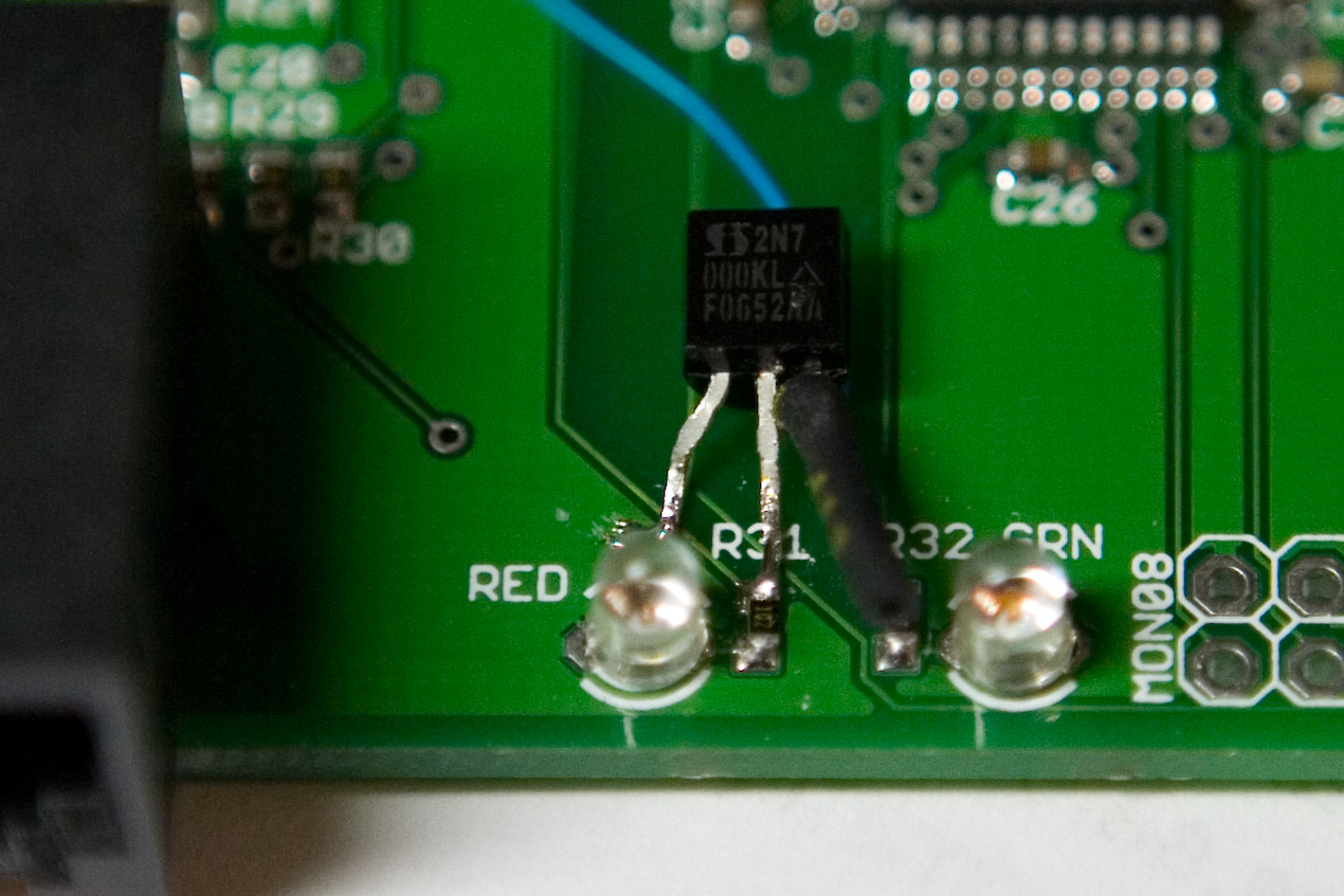
Turns out that the red "Transmit" LED lights up every time the Tracker2 lights. I used this output (marked PTC1 on Scott's T2 schematic) to also drive the gate of a 2N7000 MOSFET that I added. I connected the Drain of the new FET to Ground. This forms a "Low Side" switch that can sink ~200mA, so it can drive most relays in the 5-12V range. To implement, I soldered the Gate to the side of R31 farthest from the TX LED. I scraped off the solder mask above the ground plane just to the left of R31 and soldered the Source of the FET to Ground. I connected a jumper wire from the Drain of the FET to Pin 9 of the Radio connector.
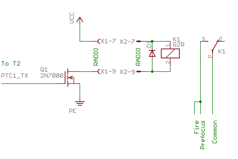
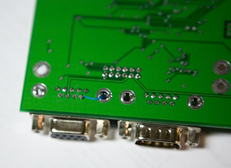
I liked having a quick-connect on the camera shutter release, so I connected the Source of the FET to pin 9 on the DB9 connector (I looked on the schematic and didn't see it connected to anything). On the Radio connector side, I connected a wire from one side of the relay coil to Pin 9 of the Radio connector, and a wire from the other side of the relay coil to the Power input to the T2 (pin 7 of the Radio connector).
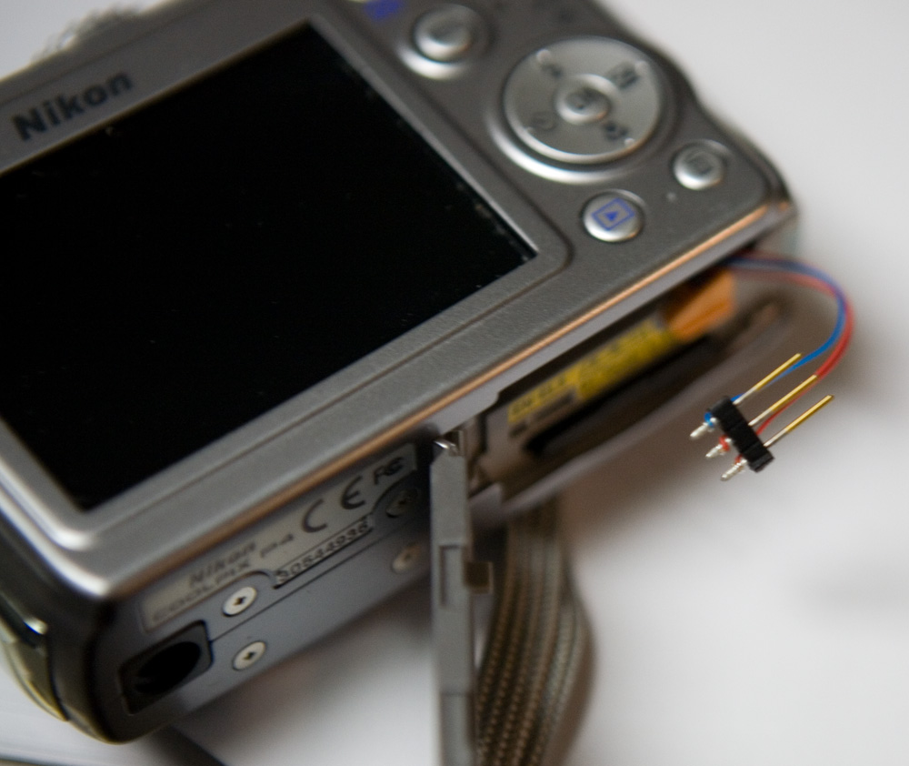
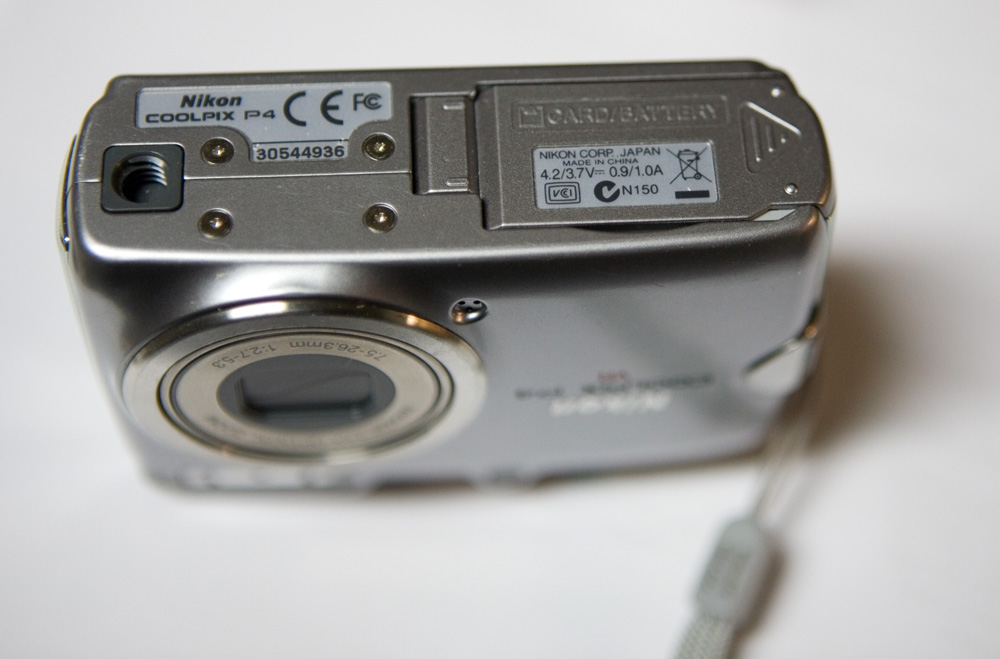
For the shutter release, I took apart my Nikon Coolpix P4 camera and soldered wires to the shutter release switch. Typically there are three wires required to fire the camera. Shorting the common to a "prefocus" lead simulates pressing the button part-way. It causes the camera to focus. At this point, shorting the "Fire" lead to the other two causes the camera to fire. In practice, just shorting all three at the same time causes the camera to focus then fire. Why connect three wires from the camera shutter release switch to the pin header connector, instead of just shorting the preflash and fire wires inside the camera, then connecting two wires? I tried this and learned the hard way that the camera focuses immediately then fires when you press the button half-way down. To allow the camera to function normally when not connected to the relay, all three are required. I placed pin header connectors between the relay and camera to allow the camera to be quickly disconnected. I make the leads out of wire wrap wire so that they can be tucked inside the cam when not in use. This lets me use the camera as it was intended - if I get it back...
Fig 1 - Camera Shutter Release Schematic
Fig 2 - Mod to T2 board
Fig 3 - Reverse Side of Board
Fig 4 - Remote Shutter Release
Figure 5 - Modified Cam is still usable