FET / IGBT High Side Gate Drive
Last Updated 12/23/2006
This is one of the most elusive subjects I've ever researched. Some pieces of info I've found that helped me understand this issue the best are:
TI App Note on Driving FETs called a target="_blank" href="http://www.ti.com/litv/pdf/slup169">slup169.pdf
IRF AN-978 Gate Drive Comparison
http://www.irf.com/technical-info/appnotes/an-978.pdf
I tried the approach of using the IRF driver ICs (at a cost of $7 each plus boards and support components, plus $100s of FETs they destroyed) and they just weren't working. It took me 6 months to figure out why: They only work within a narrow PWM duty cycle. Otherwise they can't keep up. The IRF appnote talks about providing a continuous gate drive with these ICs, but it's complicated and I just didn't trust them after all the FETs they destroyed.
I tried pulse transformers. They're heavy, they take lots of support components to implement properly, they're susceptible to stray magnetic fields turning on your FETs, and they usually only work for the designed PWM frequency. Fast turn-off requires additional passives and semiconductors, and it just took too much space. Again, it doesn't work for continuous gate drive (PWM duty cycle = 100%).
Then I found some transistor /diode circuit that was supposed to generate an isolated power supply from the high side line. It looked really complicated and I didn't use it, but it gave me the idea to use four isolated DC-DC converters to turn on each of the FETS in my H-bridge. C&D makes some ultracheap ones that are just tiny (1/4 cu in) for $8.
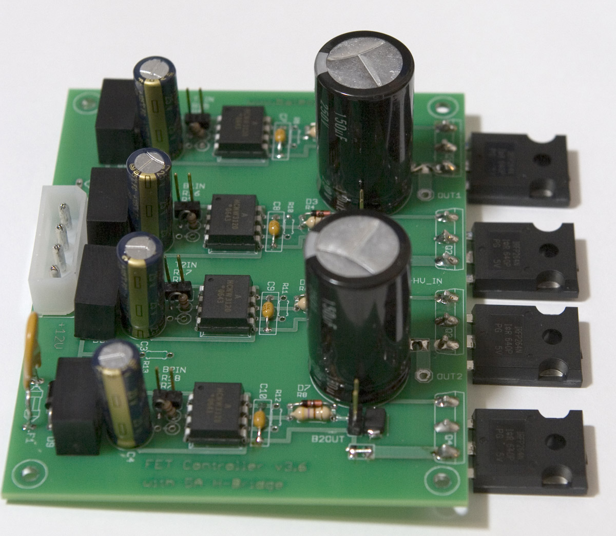
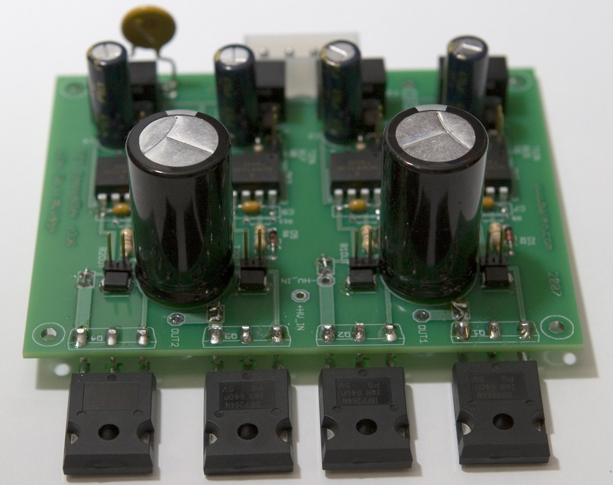
I was working with high voltage DC link, and still needed isolation for the turn-on circuitry and then needed a FET driver IC to provide the high current necessary for fast turn-on of large FETs and IGBTs. I've always heard that Optos were too slow and not well suited for this purpose, but it turns out that Agilent / Avago has some awesome optocouplers specifically for this purpose, such as the HCNW3120, and they even have FET drive circuitry built-in.Here's what I eventually came up with:
Circuit description: A 12VDC power supply powers all four converters. The 15V output of the isolated converters in turn power the output circuitry of the Agilent Optos. The Optocoupler inputs (LEDS) are powered directly from a PIC or anything with Open Collector outputs and 15mA capability. There's a gate resistor to tailor switch-on current/time in parallel with an "Anti-parallel" diode to vastly increase turn-off time. My FET driver uses four of these circuits to drive an H bridge. Only two were really necessary, but I opted for symmetry over cost to reduce the timing issues that will surely be encountered when building your own FET gate drive. It works great for H- bridges, half-bridges, it also becomes an LV/HV BLDC motor controller, HV lighting controller, all sorts of things.
If you're considering this, draw out an H bridge and make sure that you understand all of the five separate ground planes that a circuit like this really involves, and that you keep them separate!
Most of the app notes I've read came to the conclusion that FET driver ICs were the way to go, and that isolated power supply gate drive was either slow or expensive. With all the money I've wasted on FETs, gate drivers, boards and research time, I think they're totally wrong. My circuit works for 0-100% duty cycle, for DC Link voltages of 1000-3500VDC (depending on which DC-DC converter and Opto you buy).
The final boards with FETs in place are good to a switch rate of about 400KHz using 10 Ohm gate resistors instead of the ones shown in the schematic. A DC-DC converter with higher power will be required to switch faster.
The other day I was browsing the Powerex site and found a development board meant to power their FETs and IPMs. They list a schematic that was almost identical to what I describe above (they also include desat detection), so I think I'm on track here.


