Last Updated 2/9/2003
Background
This system was designed to supply electrical power to devices in an apartment or other rental property during an electrical blackout.
The most common way of permanently connecting an electrical generator to devices in the home is to have an electrician connect a generator panel to the breaker box. When the grid power goes out, the homeowner switches a switch in that panel that connects the generator to some or all circuits in the building. When the power comes back on, the homeowner switches back to grid power and shuts off the generator. However, I rent an apartment, so it isn't possible to make the modifications to the building electrical system or add solar panels to the roof. I still wanted to go off-grid, and this is my solution.
An ultra-quiet generator was the solution, but they're all really low output (<2KW) or really expensive (>$1500). I did an electricity survey and saw that I could use a combination of modified UPSes and load shedding to minimize the size of the generator I needed. I bought a Honda EU2000i 1600 Watt 49dB model which you can read about here. I tested it, and it was quiet enough to set outside on my deck without causing a disturbance. A bonus was that it weighs 46 pounds, so it was easily portable.
Next came the issue of distributing that power. Simple - an extension cord or two, right? Problem was that to run everything I normally run, I'd need three generators this size and 40 outlets to plug everything into. I was worried that I'd trip over the cords in the dark, and there was no way I was going to do all that rewiring just for the brief (~8hrs) blackouts that frequent my town. I needed a way to switch everything I wanted to power over to generator power without disconnecting and reconnecting everything. This project is my solution to that problem.
Problems I Encountered
When I bought the generator, I didn't know that I couldn't just plug in everything in all at once without causing a huge amount of strain on the generator. It caused the motor to die or the generator to flip over on its side and then die. So I needed a way to bring the load online over a period of time to allow the generator to transition from idle to full-load.
If I tried to get the generator to start several motors (refrigerator, AC, fan, heater fan, etc) simultaneously, it way overloaded the generator and the internal breaker tripped, forcing me to restart the generator to clear the overload condition. I needed to start the motors one at a time, before the rest of the load was applied.
I wanted the load to run from the wall power, but I didn't want one outlet supplying power for everything. So I needed a system that would sense when an alternate power source was available and switch each load to that source, then switch back to grid power if the alternate source was unavailable.
I wanted the load to run from grid power again only after the transients had died down. This meant determining when grid power was available and delaying the switch from generator power back to grid power for a minute or two.
I wanted to be able to power a load larger than the generator capacity for brief periods of time. Load shedding ala the TV show Green Acres was a partial solution: Turn off enough stuff and the higher-current loads (microwave / hair dryer / George Foreman Grill) can be used. Again, I didn't want to start plugging and unplugging devices, so I needed some switching mechanism. Another part of the solution was to modify some UPSes for longer run time to power those devices that needed to continue to function (computers, TV, phone, clock, etc) when the higher current devices were being powered by the generator.
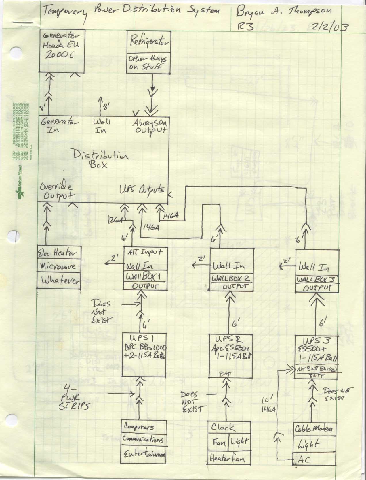
The solution to all of these was the Emergency Power Distribution System shown below.
Components of the System
Distribution Box - This waits for grid power to fail, then directs generator power to the wall switch boxes or high-current applications. When grid power returns, it waits a delay period, then switches off the power being provided by the generator. Also implemented in the distribution box is a load shed to minimize the size of the generator or inverter needed.
Wall Switch Box - This waits for generator power to become available through the alternate input on the wall switch box, then waits a delay period, then disconnects the load from the grid power and connects it to generator power. When generator power fails, the load is immediately switched back to grid power.
Uninterruptible Power Supplies - These power mission-critical devices when grid power and generator power are both unavailable. These have to be able to power connected devices until the generator can be engaged and during times when the generator power is being used by high-current devices, so they've been modified with larger batteries.
Generator - This is the main source of power during blackouts.
Extension Cords - These are necessary to connect the UPSes to the distribution box, and the distribution box to the generator. They're left in place permanently.
How these Components are Connected
Note: the ">>" symbols shown in the diagram above represent a standard 120V plug and receptacle pair
System Overview - How it works
When the grid power is available, a relay in the distribution box waits a predetermined period of time (for transients associated with power returning to the town to die down) and then cuts off any power being supplied to the wall boxes and anything connected to the override circuits through the alternate power inputs (the extension cords).
When alternate power is not available to the wall switch boxes, they supply grid power (if available) to the loads connected to the wall switch boxes.
When grid power fails, the UPSes supply power to the attached loads until the generator is started and connected to the distribution box. Once the generator comes on, that power is directed to the outputs of the distribution box. These outputs are either the UPS outputs or the Override Outputs, depending on the position of the switch on the distribution box.
When the distribution box switch is set to UPS Output, power is supplied to the alternate input of the wall switch boxes.
When power is supplied to the alternate input of the wall switch boxes, the switch boxes wait a pre-determined time, then turn on and direct the alternate power (from the generator) to the loads attached to the wall switch box outputs. The times for each of the wall switch boxes is staggered to minimize the load rate-of-change presented to the generator, and to minimize startup current in the case where the load might be multiple electric motors.
If the switch on the distribution box is switched to override, power is cut to the UPS outputs and sent to the override outlets. This is to allow for high-current devices such as a microwave, hair dryer, heater, etc. When power fails to the UPS outlets, the UPSes continue to power the loads attached to them. When the switch is returned to the UPS position, the boxes will wait the pre-determined period and then switch the loads onto the alternate input power supply again. The switch should be kept in the UPS position when possible. If the grid power returns while the switch is in the override position, the loads connected to the wall switch boxes will receive power from the grid immediately, overriding the safety delay feature of the distribution box. Since everything is plugged into a surge-suppressed UPS, this probably isn't that big of a deal.
If any power is available to the distribution box (either grid power or generator power), the Always-on outlet will supply power. When grid power is available, it supplies grid power to the Always-on outlet. Otherwise the relay switches the always-on load to alternate power input (the generator). This is essentially the same function as a wall switch box with the time-delay set to zero. I incorporated this as a supply for high-priority loads that couldn't be connected to a UPS, like the refrigerator.
When the grid power becomes available again, a relay in the distribution box waits a predetermined period of time (for transients associated with power returning to the town to die down, I chose one minute) and then cuts off any power being supplied to the wall boxes and anything connected to the override circuits through the alternate power inputs (the extension cords). When alternate power is no longer available to the wall switch boxes, the wall switch boxes direct the grid power to the loads attached to the wall switch boxes.
At this point, the system has completely reset itself to the state it was in at the start of this explanation and can function again when another outage occurs.
Future Improvements
Look at the regular relay in the distribution box. Rewire to power the coil from the generator instead of the grid power, so that if alternate power is available, it will be sent to the Always-on outlet, otherwise grid power will be sent to the Always-on outlet. This will change the priority output from grid power to generator power.
Look at changing the override circuit so that it's on for the minimum time possible. Maybe continue to power the wall switch boxes from alternate power through a current-limiting resistor (so that the TDR coils will remain energized and the loads will continue to be switched to the alternate power input instead of from the grid input). Currently, when grid power returns while the switch is set to Override output, grid power will immediately be sent to the loads attached to the wall switch boxes. Since the loads are connected to a UPS connected to the wall switch box, the loads are surge-protected and battery-backed, so it's probably not that big of a deal.
Look at ways to make all power sources (Gen/UPS/Fuel Cell/etc) available to all loads.
Implement automated time-shifting and load-shedding in the Distribution Box so that this can happen in an automated fashion.