Last Updated 03/10/2008
[an error occurred while processing this directive]
Balloon Tracking System
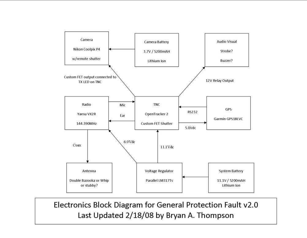
Here's what's inside the box: Radio, System Batt, TNC, Voltage Regulator, Camera, Shutter Release Relay, Camera Battery, GPS and Strobe Light
Another View
The Garmin GPS Puck is attached to the capsule lid with Silicone glue
We attached a strobe light to the top. It strobes when the TNC transmits a data packet.
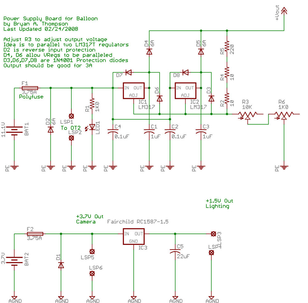
Balloon Power Supply
The design for the power supply is to have two batteries. The first is an 11.1V / 5000mAH Lithium Ion pack that powers the OpenTracker2 and radio. The second is a 3.7V / 7200mAH Lithium Ion pack that powers the camera and strobe. The idea behind this is that I don't want the camera to kill the transmitter functionality if it takes a while to get to the site. We want the transmitter operational when we get to the site to allow DF possibilities.
The voltage regulator below provides overcurrent protection on the batteries and provides the +12V for the OT2, +7V for the radio, +3.7V for the camera and +1.5V for the strobe. LED1 was removed for energy savings purposes.
Custom Cables
There are a crapload of custom cables involved in the balloon payload. See below:
Serial GPS to Tracker2 Cable
This cable connects the Garmin GPS18LVC GPS Puck to the Serial port on the Tracker2
DB9F GPS Puck
(Tracker2 Serial) (Garmin GPS18LVC)
1 - NC
2 ------------------------------------------- TXD (White)
3 ------------------------------------------- RCV (Green)
4 ------------------------------------------- +Vcc (Red)
5 ------------------------------------------- GND (Black)
6 - NC
7 - NC
8 - NC
9 - NC
This cable allows us to connect to the Garmin and program the firmware in the GPS puck:
DB9M DB9F USB A
(Computer) (GPS) (Computer - Powers GPS)
2 -------------------------------- 2
3 -------------------------------- 3
4 -------------------------------- 4 --------------------------- +5V
5 -------------------------------- 5 --------------------------- GND
Tracker2 to Radio Cable
This cable connects a Yaesu VX2-R radio to the Tracker2:
DB9M Yaesu 3.5mm 4 pin DC Power Shutter Release Relay PTT Resistor
(Tracker2) (Radio) (2 pin Adaptaplug) (2 pin jumper header) (Inside DB9 shell)
1 ---------------------------------- Ring 2 ------------------------------------------------------------------------------------------------------- 1K Resistor Side 1
2 - NC
3 ------------------------------------------------------------------------------------------------------------------------------------------------ 1K Resistor Side 2
4 - NC
5 ---------------------------------- Tip
6 ---------------------------------- Sleeve ----------------------------------- GND --------------------------- Relay Coil -
7 ---------------------------------------------------------------------------- +Vcc
8 - NC
9 ------------------------------------------------------------------------------------------------------------- Relay Coil +
Tracker2 to Camera Cable
Click Here for info about the shutter release mod we used.
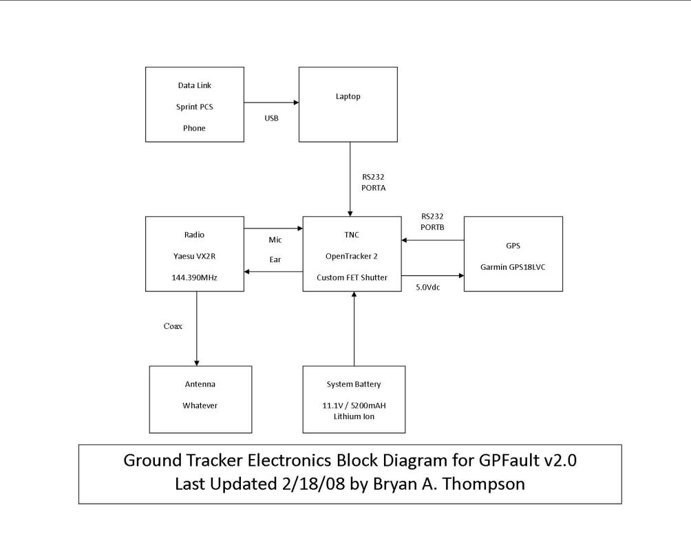
Ground Chase Vehicle Tracking System
This seems to change by the minute, but right now it looks like we're going to have a few substitutions from the block diagram shown below. The GPS is going to be a USB eTrex model. The HT is probably going to be some sort of mobile radio. We've had a really hard time getting Tracker2's, so we hope to use a Kantronics KP 3+. If not, we'll try to decode packets via laptop sound card. If not, we'll use an iPhone to track it.


